Table of Contents
Advertisement
SAFETY INFORMATION ...........................
About This Supplement .......................2
Safety Messages ....................................2
Intended Use ..........................................3
Warning Label ........................................3
Intended Use ..........................................3
Bicycle Suspension ................................3
FORK OVERVIEW ................................... 4
Rebound and Lockout .........................3
FRONT WHEEL ........................................ 6
WHEEL HUB ........................................... 8
FRONT BRAKE ........................................ 9
ADJUSTMENTS ......................................10
Suggested Air Pressure ......................10
How to Set Up Sag ............................... 11
Rebound Adjuster ............................... 12
Lockout Lever ........................................ 12
Tuning Tips ............................................ 13
Please note that the specifications and information in this manual are subject to change for product
improvement. For the latest product information, go to
READ THIS MANUAL CAREFULLY!
It contains important safety information.
Keep it for future reference.
lefty speed
dlr2 & sl
Owner's Manual Supplement
120025.PDF
CONTENTS
MAINTENANCE .....................................14
Schedule ................................................ 13
Cleaning ................................................ 13
Air Filter ................................................. 17
Frame Bumper ..................................... 17
Fork Boot ............................................... 18
Needle Bearing Migration ............... 20
XC3 SI STEM STEERER ........................... 22
SUSPENSION GLOSSARY ..................... 24
REPLACEMENT PARTS ...........................27
DLR2 DAMPER ...................................... 28
SL DAMPER ........................................... 30
TELESCOPE PARTS ................................ 32
SERVICE TOOLS .....................................33
OWNER NOTES .................................... 34
29 INCH WHEEL COMPATIBILITY ......... 36
http://www.cannondale.com/tech/.
Advertisement
Table of Contents

Related Manuals for Cannondale LEFTY SPEED DLR2


Summary of Contents for Cannondale LEFTY SPEED DLR2
-
Page 1: Table Of Contents
Rebound Adjuster ....... 12 29 INCH WHEEL COMPATIBILITY ..36 Lockout Lever ........12 Tuning Tips ..........13 Please note that the specifications and information in this manual are subject to change for product improvement. For the latest product information, go to http://www.cannondale.com/tech/. -
Page 2: About This Supplement
If you need a manual or supplement, or have death. a question about your bike, please contact your Cannondale Dealer immediately, or call us at one of the telephone numbers listed CAUTION on the back cover of this manual. -
Page 3: Intended Use
If it is missing or damaged, especially at high speed and in advanced you can obtain a free replacement from terrain, you risk severe injury or death in Cannondale. a crash. • Ride at reduced speeds. • Learn the performance characteristics... -
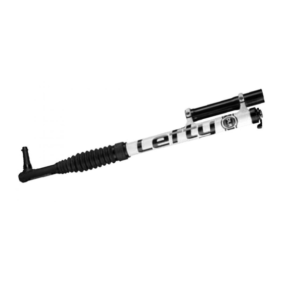
Page 4: Fork Overview
fork overview ��� ��� dlr2 and dlr sl Steerer Tube ��� ��� ��� Lockout Lever Rebound Knob Outer Collar ��� ���� Upper Clamp Outer Tube ��� Bumper Lower Clamp ��� Cable Guide ��� Zip Tie ���� Boot Spindle Brake Mounts (6” IS Standard) Air Filter Assembly Clamp Bolts ���... - Page 5 120025.PDF dlr2 and dlr sl rebound & lockout assembly 1.5mm 2.0 N•m 18.0 In•Lbs 10mm 5.0 N•m, 44.0 In•Lbs Use a Shimano TL-FC32 Crank Adapter Installation Tool (Shimano Y-130 09210) to remove and install. CAUTION: DO NOT LOOSEN (10) OR TIGHTEN THIS NUT!!! “TOP”...
-
Page 6: Front Wheel
Note brake alignment shims between front wheel Lefty brake bosses and the caliper. REMOVAL 4. Turn hub bolt (1) counter-clockwise to remove the hub from the spindle. 1. Place bike in a work stand with front NOTE: As the bolt is turned counter- wheel off the ground. - Page 7 Wipe all parts clean with a dry shop the caliper bolts. towel and apply a high-quality bike grease to: USE ONLY 16 MM (Cannondale kit # LEFTYBOLTS. Longer bolts can result in I.D. of the larger hub cartridge bearing . contact with the brake rotor causing Both spindle bearing lands .
-
Page 8: Wheel Hub
wheel hub... -
Page 9: Front Brake
Make sure the brake disc can not make Mount the front brake caliper using the 16 contact with the fork boot. A rotating brake mm bolts of Cannondale kit LEFTYBOLTS. disc can wear through the boot allowing See next figure. -
Page 10: Adjustments
adjustments Suggested Air Pressure To set pressure, remove the valve cap at the bottom of the fork. Set the pressure according to rider weight. Use a bicycle suspension pump. Consult the table below. Stay within the pressure limits. At the bottom of the fork: Pressure Limits MIN. -
Page 11: How To Setup Sag
The damping cartridge negative spring of both Lefty DLR2 and CARBON SL forks is specific to the rider weight. See table below. If you find that you set the air pressure much higher or lower than suggested, we recommend the corresponding negative spring for best performance. Ask your Cannondale Dealer about negative spring kits for your fork. -
Page 12: Rebound Adjuster
FW D... -
Page 13: Tuning Tips
120025.PDF Suspension Tuning Tips Condition: Possible Solutions: Lower air pressure; softer compression Not using full travel, feels harsh, poor damping; lighter negative spring; damper cornering traction revalve Increase air pressure or stiffer coil springs; Bottoms out, soft throughout travel, firmer compression damping; revalve excessive sag Harsh over large bumps, but good over Softer compression damping;... -
Page 14: Maintenance
It should also include any work described in technical bulletins or product recalls. Our “Factory Tech Room,” (in the USA) provides professional services through Cannondale dealers for Headshok suspension forks . Please ask your dealer about the service programs... -
Page 15: Cleaning
FORK PROBLEMS The following are conditions that can indicate a serious fork problem: If you find one, don’t ride the fork. Have the fork inspected by your Cannondale Dealer and any problems corrected first.` 1. Any unusual “klunking” or knocking noises 2. - Page 16 IMPORTANT INFORMATION ABOUT RIDING IN WET, VERY HUMID, OR COASTAL CONDITIONS The Cannondale Headshok needle bearing system uses precise components such as bearings and races that are made of high strength steel. These components require proper maintenance before and after riding in severely wet conditions.
-
Page 17: Air Filter
120025.PDF Air Filter The air filter assembly is located over two Use air filter holes in the outer tube. Air passes in and oil foam. out of the ports as the fork moves. FOAM ELEMENT The air filter assembly stops the passage of dirt and water which would damage the internal fork components. -
Page 18: Fork Boot
The fork boot protects the internal parts ties, and cable clamps are available (inner tube, races, lubricant, needle bearings, through a Cannondale Dealer. and other internal parts) from contamination and damage. It is a barrier to water, dirt, If you find boot damage, the area under dust, mud, or grit encountered while riding. - Page 19 120025.PDF Wipe away any old grease with the fork and carefully re-apply grease. a clean lint-free shop towel. Cycling moves the new grease inside Cycle the fork and repeat. the fork onto the outer tube races and bearing cages. Its OK to leave CAUTION a good coating under the boot.
-
Page 20: Needle Bearing Migration
Needle Bearing Evidence of migration is: Migration Reset An unusual "top out" noise .If an unusual noise is heard, the extended fork length should be measured to confirm the condition. NOTE: Ideally, reset the bearings after 25 hours of normal riding or 10 hours of hard The fork’s maximum extended riding/racing to maintain optimum fork length is reduced. - Page 21 120025.PDF Resetting Migrated Needle Bearings Place the bike in a work stand. Release all the air pressure through the Schrader valve. Remove the rebound knob and lockout lever. Remove the outer cap with the Shimano bottom bracket tool TL-FC32. See page 5. Compress the telescope and remove the two split rings from the top cap..
-
Page 22: Xc3 Si Stem Steerer
(next page). 3. Position the Lefty clamps onto the headtube as shown. 4. Insert Cannondale specific tool KT020/ through the bottom clamp, into the head tube, and out the upper clamp. 5. Make sure the plastic ring (6) is on the stem. - Page 23 120025.PDF SIZE H-BAR DIA. DATE LENGTH ANGLE O-Ring (lubricate) Stem Handlebar clamp Clamp boltsr Plastic ring Seal Upper Bearing Bearing cup Steerer bolt Notes: Ensure that the plastic ring (6) is WARNING on the stem before inserting into head tube. The steerer bolt (10) is a When you tighten or loosen the structural part and must...
-
Page 24: Suspension Glossary
Bottom Out - When the front or rear suspension suspension fully compresses to absorb a bump or jump landing. A hard stop is usually glossary felt at bottom out. Top Out - When the front or rear suspension Damping - The process of dissipating energy fully extends after absorbing a bump or jump and slowing down the suspension motion. -
Page 25: Replacement Parts
1/2” Shaft clamp for clamping damping cartridge shaft ● ● HDTL168/ Bullet tool for installing oil caps into damping cartridge For an up to date list of kits available for your bike, please visit our Tech Center at : http://www.cannondale.com/tech/... - Page 26 LEFTY ORDER DESCRIPTION DLR2 DLR SL Damping Cartridge Parts ● KF200/BLK Negative spring X-FIRM ● KF200/BLU Negative spring STANDARD ● KF200/GRN Negative Spring, SOFT ● KF200/RED Negative spring FIRM ● KF201/BLK Complete damping cartridge w/ X-FIRM negative spring ● KF201/BLU Complete damping cartridge w/ STANDARD negative spring ●...
- Page 27 120025.PDF DESCRIPTION ORDER H-Bar dia. Stem Stem Color (mm) Rise° Length ( mm) XC3 Stem-Steerer QSD090-5318/BBQ 31.8 QSD100-5318/BBQ 31.8 QSD120-5318/BBQ 31.8 QSD09005318/BBQ 31.8 QSD10005318/BBQ 31.8 QSD12005318/BBQ 31.8 QSD09020318/BBQ 31.8 QSD10020318/BBQ 31.8 QSD12020318/BBQ 31.8 XC3 Stem QSC11020318/BBQ 31.8 QSC13020318/BBQ 31.8 QSC09020318/BBQ 31.8 QSC08005318/BBQ 31.8...
-
Page 28: Dlr2 Damper
dlr2 damper... - Page 29 120025.PDF...
-
Page 30: Damper
sl damper ITEM DESCRIPTION TOP OUT SPRING THRUST WASHER 2-010 O-RING 6.07 ID X 1.78 W 2-018 O-RING 18.77 ID X 1.78 W 2-111 O-RING 10.77 ID X 2.62 W O-RING 2.00 ID X 1.00 W O-RING 3.00 ID X 1.00 O-RING 9.00 ID X 1.00 W O-RING 9.00 ID X 1.00 W O-RING 8.00 ID X 1.50 W... - Page 31 120025.PDF PISTON...
-
Page 32: Telescope Parts
telescope parts WARNING HIGH PRESSURE HAZARD – Do not attempt to service a pressurized fork. You can severely injured or killed by pressurized (forcefully) ejected fork parts. Release pressure before performing any work. ITEM DESCRIPTION SCHRADER CAP SCHRADER CORE SPLIT LOCATING RING TOP CAP SEAL PLASTIC 2-019 O-RING 20.35 ID X 1.78 W 2-020 O-RING 21.95 ID X 1.78 W... -
Page 33: Service Tools
120025.PDF cannondale service tools HDTL146/ - Castle Tool HD187/ - 1/2 in Shaft Clamps HDTL168/ - Bullet Tool... -
Page 34: Owner Notes
owner notes Record maintenance history, service, or set up information . DATE WORK PERFORMED... - Page 35 120025.PDF...
-
Page 36: 29 Inch Wheel Compatibility
Do not install a 110mm travel lefty onto a bicycle frame designed for 29 inch wheels. If you have any questions, please ask your Cannondale Dealer for help. YOU CAN BE SEVERELY INJURED, PARALYZED OR KILLED IN AN ACCIDENT...