Only 1 channel is described, the other channel works the same.
Power Supply Rectifier - Bridge Rectifier D1 ( GBU1010 or GBU810 ) is used to rectify the incoming
AC Voltage in to DC, the DC is Further smoothed by Capacitor C1 and C2 ( 4700uf 50v )
Amplifier - Main job of amplification is done by ic U1 and rest are the supporting components.
Input signal is fed to pin no.3 (Non Inverting Input) through R1 & C3. R2 defines the input impedance.
R3 & R4 connected to Pin no.2 (Inverting input) set the closed loop gain. Changing the value of any one these resistors will change the gain of the amplifier.
Pin no.9 (Stand by) - R7 keeps ic U1 in active mode by providing positive voltage.
Pin no. 7, 13 are positive supply, Pin no. 8, 15 are negative supply and 1, 4 are ground pins. Pin no.14 is the output pin.
Mute Function - Pin no.10 (Mute) is connected to JP2. To use the mute function replace JP2 with a switch.
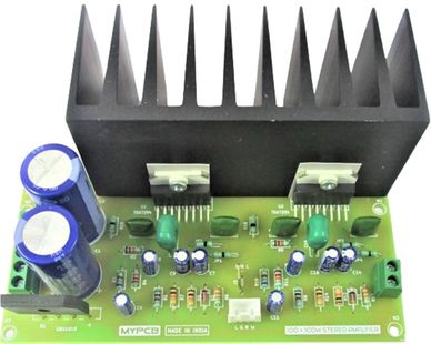
Metal Tab of ic U1 is connected to negative supply internally, so proper insulation is necessary when fitting ic U1 on heatsink.